Battery Management System for Charge CCCV, Inc.
Battery Management System for Charge CCCV, Inc.
Jonathan Donovan
Table of Contents
I. Introduction
1.1 Problem Definition
1.2 Current Solution – Battery Management System
1.2.1 Electrical, Thermal, and Safety Management
1.2.2 State of Charge and State of Health Determination
1.2.3 Cell Balancing
II. Research
2.1 Off-The-Shelf BMS
2.1.1 Implementation
2.1.2 Experimentation
2.1.3 Compatibility and Results
2.2 Battery Cycling and Characterization
2.2.1 Implementation
2.2.2 Experimentation
2.3 Equivalent Circuit Modeling of a Battery
2.3.1 Theory
2.3.2 Implementation
2.4 Additional Research
2.4.1 Coulomb Counting and State of Charge Simulation
2.4.2 3D Modeling and Printing
III. Conclusion
3.1 Results
3.2 Next Steps
I. Introduction
1.1 Problem Definition
Lithium-ion batteries are commonly used in consumer electronics, such as smartphones and laptops, or used in large electronics, such as electric and hybrid vehicles. Although the batteries are used very frequently, they can actually be quite dangerous if handled improperly. Each lithium ion battery has a predetermined safe operating region described by certain characteristics, including voltage, current, power, and temperature. There are maximum and minimum voltage and temperature levels, as well as maximum current and power output levels. If the parameters are not kept within their thresholds, harmful effects can occur to the battery, the device, and possibly the user.
Overcharging, the process of charging a battery beyond its maximum voltage and current limits, especially at cold temperatures, can lead to lithium plating. Lithium plating is the process of lithium metal accumulating on the anode during the intercalation process, reducing the amount of free lithium ions and causing permanent capacity loss. It is more likely for lithium plating to occur at cold temperatures because the electrochemical reactions that occur within a battery at cold temperatures are much slower than the reactions in a battery at warm temperatures. Due to their slowed reactions, the electrodes cannot react quickly enough to the excessive charge flow from overcharging.
An accumulation of lithium metal can also lead to the penetration of the separator in the lithium-ion battery. A separator is a material within a lithium-ion battery that separates the two electrodes, but allows for the flow of ions, i.e. lithium ions. The penetration of the separator results in a short circuit, which can ultimately lead to overheating and thermal runaway. Thermal runaway is a dangerous process in which a battery overheats excessively until an explosion or fire occurs. Additionally, overdischarging, the process of discharging a battery below its minimum voltage limit, can lead to permanent capacity loss because a breakdown of the electrodes occurs.
As one could see, there are many ways in which lithium-ion batteries can fail. To control these electrical and thermal characteristics of lithium ion batteries, a battery management system (BMS) is integrated into the electronic device.
1.2 Current Solution
The key features of a battery management system are electrical, thermal, and safety management, battery state determination, and cell balancing.
1.2.1 Electrical, Thermal, and Safety Management
Battery packs can consist of several batteries, typically referred to as cells, in series or parallel configurations. A battery pack consisting of more cells can require more complex battery management systems. Therefore, several sensors may be required depending on the number of cells and their configuration in the battery pack.
As stated above, voltage and current are two vital electrical parameters that must be monitored and controlled continuously while lithium-ion batteries are charging or discharging to prevent damage to the batteries or user. A voltage sensor can monitor the voltage of a battery and a current sensor can monitor the current output or input of a battery. Switches and relays are also typically integrated to control the charging and discharging cycles.
The temperature of the battery pack, as well as the individual cells, must also be monitored and controlled. Thermistors or thermostats can monitor the temperature of a battery pack, and fans or ventilation can control the temperature of the battery pack. Fans can cool the battery pack while the ventilation can provide paths for heat dissipation. Fans can be also be controlled using switches or relays.
Redundant safety mechanisms are typically implemented in a BMS to prevent dangerous conditions. These mechanisms include internal and external fuses for excessive current or temperature, voltage isolation, and electronic current limiting.
1.2.2 State of Charge and State of Health Determination
State of charge (SOC) and state of health (SOH) are used to analyze the state of a cell or battery pack. State of charge is referred to as the fuel gauge of a battery pack; that is, how much usable charge or energy that the pack can provide with respect to its full capacity. 100% SOC means that a cell is completely full while 0% SOC means that a cell is empty. State of health, on the other hand, is irreversible and commonly associated with the lifespan of the battery. SOH can be estimated using different parameters, including the number of cycles a battery has completed, its self-discharge rate, and its internal resistance.
The SOC can be estimated by measuring the voltage or current of the cell or pack. Voltage profiles can be created, correlating pack voltage with SOC. Therefore, by measuring the voltage of the pack at any moment, an estimated SOC associated with the voltage level could be obtained. However, this method cannot be used for many battery chemistries with flat voltage profiles. Lithium-ion batteries, such as lithium iron phosphate, maintain a constant voltage during most of their voltage profile. This means that their operating voltage may be the same at 20% SOC and at 80% SOC.
Another common method of estimating the SOC of a battery pack is coulomb counting. If both the total capacity and the current capacity of the battery pack are known, then the SOC can be estimated by measuring the current flow into or out of the battery pack. Current is the flow of charge over time, specifically Coulombs per second. The total capacity is the total amount of Coulombs that a battery can hold. If we know the current amount of Coulombs in the battery pack, then we can measure how the SOC changes as current flows into or out of the battery pack. By integrating the current flow into or out of the battery pack over time, the amount of charge flowing into or out of the battery pack can be determined.
Coulomb counting is more precise than analyzing the voltages of cells with flat-voltage profiles, but it also has challenges. The first challenge is that someone may not know the initial capacity of a battery. Therefore, the battery may need to be fully charged or discharged first to know its initial capacity. In other words, one needs to know the battery’s initial SOC to properly track the changing SOC. Also, batteries may suffer from long term drift, in which self-discharge rates change the current SOC of the batteries. As batteries age, their internal resistance increases and they have less usable capacity. This can also affect the current SOC in the battery. Therefore, the initial SOC would have to be reset before executing Coulomb counting. My research included reviewing these SOC estimation algorithms and learning about other algorithms.
1.2.3 Cell Balancing
An important feature of a battery pack is that it may contain multiple cells in different configurations. If multiple cells are used within a battery pack, there is a high probability that they can become imbalanced as they cycle. For example, five cells in a series configuration will provide a specific current when discharging into a load. However, the cells may not all provide the same amount of charge. Over time, this phenomenon can lead to an imbalance in the pack and greatly reduce the SOC of the battery pack.
For example, let’s say that there are five cells in a series configuration. One cell has 80% SOC, one cell has 20% SOC, and the other three have 50% SOC. Ideally, as the pack charges, the cell with the highest SOC will reach 100% while the others reach 40% and 70%. However, the pack can no longer charge because the maximum cell voltage has been reached. If the pack is then discharged, the cell with the lowest SOC will reach 0% while the others reach 60% and 30%. The pack can no longer be discharged because the minimum cell voltage has been reached. If the pack is charged again, then it will only be able to charge 40% SOC because a maximum cell voltage will be reached again. Therefore, only 40% of the battery pack’s total capacity can actually be used. In order to efficiently use the full capacity of a battery pack, it is crucial to maintain a balanced SOC across the cells. It is also important to use cells with the same total capacity.
To maintain the same SOC across all of the cells in a pack, a battery management system executes passive or active cell balancing. Passive cell balancing is the process of dissipating the energy from the cell with the highest SOC through a shunt resistor. As a result, the cell’s SOC will decrease and eventually reach the same SOC as the other cells. Active cell balancing is the process of transferring energy from the cell with the highest SOC to the cell with the lowest SOC, or to the rest of the cells in the battery pack using switches and capacitors. As one could imagine, passive cell balancing is cheaper and simpler to implement than active cell balancing. However, active cell balancing is much more efficient than passive cell balancing.
II. Research
2.1 Off-The-Shelf BMS
My research focuses mainly on the implementation, control, and analysis of a BMS. Since I collaborated with Charge CCCV, Inc. through a Strategic Partnership for Industrial Resurgence (SPIR) program, my research included a practical integration of an off-the-shelf BMS with lithium ion batteries. Charge CCCV, Inc. bought an Orion BMS and I was tasked with researching the unit and implementing it with five LiFePO4 cells. The Orion BMS has several versions that are compatible with different number of cells. Our unit was compatible with 24 cells. Once setup with external circuitry, including relays, chargers, and loads, the BMS recorded various characteristics of the lithium-ion cells as they charged and discharged.
2.1.1 Implementation
A battery management system is commonly used to communicate with smart chargers, smart loads, and the battery pack. By smart, I mean that the chargers and loads contain a type of technology, such as a microprocessor, which allows them to communicate with a BMS. The BMS would normally be programmed to communicate the current limits, the cell voltage limits, and the pack voltage limits to the smart charger or smart load, such that they control the battery pack’s cycling. However, I did not use a smart charger or load. Instead, I used an 18V AC-DC unregulated power adapter as the charger and a simple 15 ohm resistive load. Therefore, I had to implement external circuitry that the BMS could communicate with to control the battery pack’s cycling. A simplified integration can be seen below.
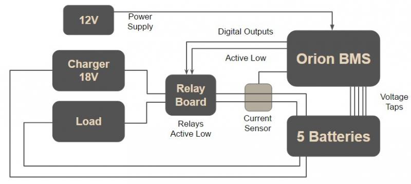
Figure 1: Simplified Orion BMS Implementation
I integrated a relay module board with the BMS, charger, load, and battery pack. The Orion BMS was powered by 12V from an additional AC-DC power adapter. The 12V was sent through a resistor to power the relay board, but this was not shown in the diagram above. The resistor acted as voltage divider and limited the voltage powering the relay board to 5V. The Orion BMS was programmed with an Orion BMS utility. I utilized its digital outputs, which were active low; that is, the digital outputs pulled down to ground when they were activated. The relay module had four SPDT relays, each of which were also active low. This means that the relays would turn on when the corresponding IN pins were pulled down to ground on the board.
Two relays were used: one for charging the battery pack and one for discharging the battery pack. I used the digital outputs – charge enable and discharge enable – to control the relays. When the batteries were at 0% SOC and ready to charge, the BMS turned on the charge enable pin. The relay that connected the charger to the battery pack turned on because the corresponding input on the relay board was pulled down to ground by the charge enable pin. Similarly, when the batteries were at 100% SOC and ready to discharge, the BMS turned on the discharge enable pin. The relay that connected the load to the battery pack turned on because the corresponding input on the relay board was pulled down to ground by the discharge enable pin. The BMS had a hall-effect current sensor that measured the current flow into or out of the battery pack, estimating the SOC of the battery pack through Coulomb counting. Initially, the current SOC of the pack was unknown and the pack needed to be fully discharged to obtain a reference point. The BMS also monitored the individual cell voltages and executed passive cell balancing with the voltage tap wires shown in the diagram above.
2.1.2 Experimentation
After several experiments, I learned about many features of the Orion BMS. The Orion BMS had a variety of useful programmable functions, including controlling the SOC estimation, controlling cell balancing, controlling digital outputs, and much more. I could set the total capacity of the battery pack, the maximum and minimum cell voltage and pack limits, the maximum current limit, and the number of cells in the pack. I could also set the cell voltage at which cell balancing would begin. The Orion BMS required that you specify the minimum voltage difference between the cell with the highest SOC and the cell with the second highest SOC for cell balancing to execute. The Orion BMS offered the option to set SOC drift points, in which various voltage levels corresponded with various SOC levels. This could be useful for resetting the reference points for SOC estimation. If the batteries suffer from long term drift, the Coulomb counting could be reset by the SOC drift points. The Orion BMS also enforced discharging and charging current limits by turning off digital outputs. For example, if a cell voltage reached the maximum cell voltage while the pack was charging, the charging current limit would drop to 0A, and the digital output charge enable would turn off. This was how the Orion BMS could control charging and discharging the pack.
2.1.3 Compatibility and Results
The Orion BMS was compatible with lithium-ion batteries. It monitored various electrical and thermal characteristics and displayed all of the information in an organized table referred to as “live cell data”. The BMS also had a graphing interface, which could plot various characteristics of the battery pack over time. The Orion BMS recorded all of the data if programmed to and could export the data into excel files. Below is a plot of the cell voltages while the pack was charging. The BMS also performed cell balancing, which can be seen by the cell voltages converging. I recorded the data and plotted it in MATLAB. Thus, this is not the actual interface seen in the Orion BMS utility.

Figure 2: Example of Orion BMS Executing Cell Balancing
Five LiFePO4 cells were charged by the AC-DC adapter while the BMS recorded the cell voltages. Initially, the voltages rose because the charging voltage is always higher than the open-circuit voltage. However, cells 2-5 maintained a relatively constant voltage while cell 1’s voltage began rising. I allowed the cells to become imbalanced so that I could see the effect of the Orion BMS’ cell balancing. As you can see above, cell balancing began and the first cell’s voltage did not reach its maximum voltage of 3.8V. Instead, its voltage began dropping. Cell 5’s voltage also began to rise because it was clearly more charged than cell 2-4. Again, the Orion BMS executed cell balancing and began dissipating energy from cell 5. The cell balancing continued until all of the cell voltages converged. The cell voltages never rose to their maximum voltages because the charger did not have a high enough voltage to supply the cells with enough power.
2.2 Battery Cycling and Characterization
Before operating the Orion BMS, I characterized the batteries that I would be testing. Battery characterization was performed by cycling a battery under different conditions to understand how the battery would normally behave. I needed a control group, or a reference for the battery’s behavior before testing them with the Orion BMS. Otherwise, I would never know if the Orion BMS was properly recording the data. I performed battery characterization cycling tests with a BioLogic Cycler.
2.2.1 Implementation
The BioLogic Cycler had a voltage range of 10V so I could only cycle up to two cells at once. Also, all of the batteries should have ideally behaved the same way under load if they had the same chemistry and manufacturing. Therefore, I simply tested one LiFePO4 cell. The BioLogic Cycler was programmed with EC-Lab software. I could develop different cycling profiles, in which the cells were cycled a certain amount of times for different currents. The cycler also performed “Galvanostatic Cycling with Potential Limitation”, which was the same thing as constant current constant voltage (CCCV) charging.
A common charging technique used with lithium-ion batteries is CCCV. The batteries are charged to a specific maximum voltage at a constant charging current. Once the maximum voltage is reached, the cell voltage is held constant while the charging current decreases to 0A. Through this process, lithium-ion batteries are efficiently charged. In the experimentation section, I show plots of the data that the BioLogic Cycler recorded during a cycling test. However, CCCV was not performed in these specific tests. I performed CCCV tests with other batteries with the BioLogic Cycler, but have not shown the data here.
2.2.2 Experimentation
I also exported the data from the BioLogic Cycler and plotted it in MATLAB. The first plot shows the voltage of a single cell during two cycles; that is, two discharging periods and two charging periods. As you can see here, the LiFePO4 cell had a maximum cell voltage of 3.8V and a minimum cell voltage of 2.7V. The second plot shows the current flowing into or out of the battery pack. One can see that the current was constant during each cycling period.
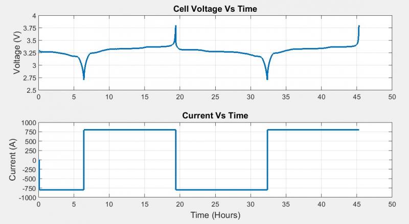
Figure 3: Cell Voltage and Current vs. Time Recorded by BioLogic Cycler
The plot below shows the cell voltage over its full capacity. As you can see here, the LiFePO4 cell had a relatively constant voltage for most of its capacity. The capacity was recorded as Ah, amp-hour, which is another unit for charge. If a battery has a capacity of 1 Ah, it is supposed to be able to provide a constant 1A for 1 hour to a load. This terminology is typically used for batteries because it is easier to understand than the number of Coulombs left in the battery pack.
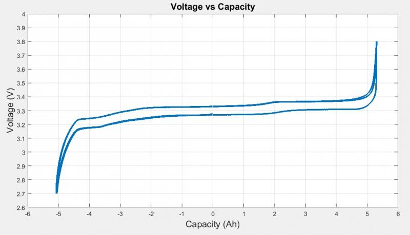
Figure 4: Cell Voltage vs. Capacity Recorded by BioLogic Cycler
The BioLogic Cyler was useful for cycling cells at different current levels. I have not shown the data here, but I found that as discharging currents increased, the cell’s capacity would decrease. A cell would not be able to provide its typical full capacity if discharged at a current much higher than its nominal current rating. I also was able to see how pressure affected individual cells. It seems that cells perform better when they have uniform pressure applied to them.
2.3 Equivalent Circuit Modeling of a Battery
2.3.1 Theory
Lithium-ion batteries exhibit non-linear behavior, making it difficult to create algorithms that accurately predict their behavior. A common method of modeling a lithium-ion battery is electrical equivalent circuit modeling. An equivalent circuit model can be designed to simulate the same behavior of a battery. Battery management systems can use this model to estimate the state of charge of a battery and compare predicted behavior with experimental data of a real battery to provide control efforts. Below is an example of a simple electrical equivalent circuit model with 1RC parallel branch.
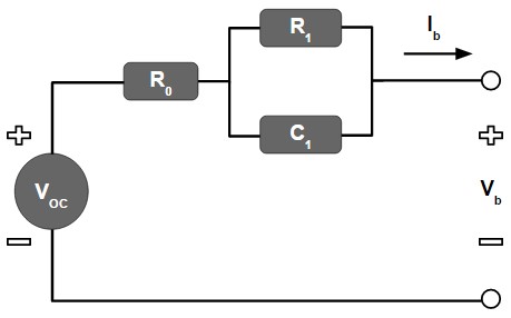
Figure 5: 1RC Branch Electrical Equivalent Circuit Model of a Battery
The circuit above contains several crucial elements: R0, R1, C1, and VOC. All of these components are functions of state of charge. As the SOC of a battery changes, the values of the components within the circuit are also changing. This is how the circuit can model the same performance as the battery. Typically, the equivalent circuit model is used to simulate a battery’s response to discharge and charge pulses. R0 is responsible for demonstrating the instantaneous response of the battery to the charger or load. As I mentioned previously, a battery’s voltage immediately increases when it begins charging, or immediately decreases when it begins discharging. R1 and C1 are responsible for demonstrating the dynamic behavior of the battery. An equivalent circuit model can contain more than one RC parallel branch; it has been shown that more parallel RC branches, in fact, can more precisely simulate a battery’s performance. VOC is simply the open-circuit voltage of the battery as a function of SOC.
2.3.2 Implementation
To implement the equivalent circuit model, I used the software tool Simulink. I found an example of a model created in Simulink by Mathworks, but I wanted to attempt to create a simpler version. The model can be seen below, but it should be noted that the model is not yet complete. The Simulink model is supposed to use parameter estimation to populate lookup tables with values for the different components in the model. The values of the lookup tables should change as SOC changes. These lookup tables are connected to variable components in the circuit such as R0, R1, C1, and Em. Em is the same thing as VOC. The lookup tables should in theory change the variable components as the SOC changes. The SOC is calculated by integrating the current flowing through the circuit. This can be seen by the integrator that is connected to the current sensor. The RC1 block is actually a subsystem, which can be seen below the first Simulink model. RC is actually the time constant tau. Therefore, the values of the capacitor can be obtained by dividing tau by the R1 value.
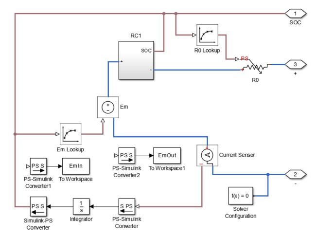
Figure 6: Equivalent Circuit Model Implementation in Simulink
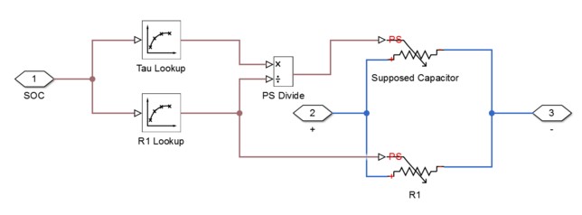
Figure 7: Subsystem RC1 in Equivalent Circuit Model in Simulink
2.4 Additional Research
2.4.1 Coulomb Counting and State of Charge Simulations
I was tasked with implementing Coulomb counting in Simulink. To do so, I created a charging and discharging circuit for a battery. Simulink has a battery block that has various parameters. I set its nominal ratings and created the circuit with various switches. The cycling was controlled by pulse generators that coordinated with each other based on time. This circuit can be seen below.
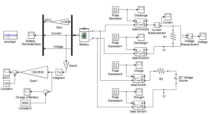
Figure 8: Charging and Discharging Circuit with Coulomb Counting in Simulink
The lower left half of the model shows the Coulomb counting circuit. The current is sent through an integrator block, which outputs the number of Coulombs flowing into or out of the battery. The output is sent through a gain 100/3600, which simply normalizes the output to a percentage for SOC. A constant “100” is added such that the SOC begins at 100% and drops towards 0%. The SOC can be seen in the second plot.

Figure 9: SOC of a Battery Charging and Discharging in Simulink
2.4.2 3D Modeling and Printing
I also designed and printed a 3D battery case for a single cell. Charge CCCV, Inc. needed a battery case for a single cell for an energy conference. I used 123D Design to create the following design.

Figure 10: 3D Model of Single Cell Battery Case in 123D Design
After several tests, I printed the following two halves of the case using a Dremel 3D printer. The case was later sealed with epoxy glue.

Figure 11: Battery Case Printed by a Dremel 3D Printer
III. Conclusion
3.1 Results
In conclusion, the Orion BMS provided the monitor and control functions needed for electrical management, thermal management, and safety management, and was compatible with lithium-ion batteries. The Orion BMS was also able to calculate the SOC of the pack and plot various parameters with its software. It had various different methods of communication and could enforce charging and discharging. Although the Orion BMS was very useful, I don’t believe the Orion BMS was the best suited battery management system for the batteries that I was testing. The Orion BMS was designed for battery packs with higher capacities, such as battery packs for electric vehicles. The Orion BMS offered a CANBUS interface for communication with external devices. CANBUS is a protocol typically used with vehicles, which is why it makes sense that the Orion BMS is meant for higher capacity battery packs. For the Orion BMS to operate properly, the battery pack needed to contain at least four cells and have a minimum group voltage of 12V. This clearly shows that the BMS was not meant for low voltage cells. The Orion BMS also could not plot current with more precision than 0.1A increments. Since I was using a lower capacity battery pack, I was using low current to charge and discharge the pack. The current could not be accurately plotted in the BMS software. The Orion BMS is suitable for low capacity battery packs if high precision is not necessary, but it is even more suitable for high capacity battery packs.
3.2 Next Steps
One future plan for the project is to design a battery management system more suited to the batteries that I was testing. The BMS should also be a relatively affordable solution and provide similar functions to the Orion BMS. Another future plan is to complete a working electrical equivalent circuit model that can simulate our specific battery’s performance. The model could then hopefully be used by the BMS to predict the battery’s performance and estimate the SOC of the battery as it charges and discharges.