Development and Implementation of a Battery Cycler
Spring 2016
Jonathan Donovan
Table of Contents
I. Introduction
1.1 Motivation
1.1.1 Lithium-Ion Battery Charging
1.1.2 Battery Cycling
II. Research
2.1 Constant Current Constant Voltage (CCCV) Charger
2.1.1 Implementation
2.1.2 Experimentation and Results
2.2 Battery Characterization – Internal Resistance Tests
2.2.1 Implementation
2.2.2 Experimentation and Results
2.3 Customized Cycler
2.3.1 Implementation
2.3.2 Experimentation and Results
III. Conclusion
3.1 Results
3.2 Next Steps
IV. References
I. Introduction
The following independent study is a continuation of the Battery Management System Research Project completed in Fall 2015. This study was initially proposed for Spring 2016 with the intention of acquiring a constant current/constant voltage (CCCV) charger and cycling Charge CCCV’s cells with an Orion BMS. However, the study expanded into other topics, including the implementation of a battery cycler and tests for measuring the internal resistance of a battery pack. The main objective of the independent study was to develop a cycler for a battery pack. In the following sections, I will discuss the motivation for acquiring a CCCV charger and developing a battery pack cycler.
1.1 Motivation
1.1.1 Lithium-Ion Battery Charging
Lithium-ion batteries are sensitive to various electrical and thermal characteristics, including voltage, current, power, and temperature; in fact, if these battery characteristics are not maintained within a specific safe operating region, a battery can be damaged and possibly dangerous to its environment. To avoid damaging a battery, manufacturers specify certain constraints, such as a maximum and minimum voltage, current, power, and temperature, to be followed. If a battery is charged to a voltage beyond its maximum voltage, then high currents can lead to lithium plating. Lithium plating is the process of lithium metal accumulating on the anode because the battery cannot respond to the high rate of lithium ions flowing. The accumulation of lithium metal can pierce the separator inside of the battery, cause a short circuit, and lead to thermal runaway and fire. If the separator is not pierced, the accumulation of lithium metal can still limit the number of free lithium ions involved in the intercalation process, severely limiting the battery’s capacity. If a battery is discharged to a voltage below its minimum voltage, its electrodes can breakdown and permanently reduce its capacity.
Batteries are also very sensitive to current flow and temperature. High temperatures reduce a battery’s capacity because the chemical reactions within the battery speed up. In addition, high temperatures can also lead to a battery overheating. Low temperatures, on the other hand, decreases the rate of chemical reactions inside of a battery. As a result, a battery may not respond quick enough to high current flow, leading to lithium plating. I will not discuss the temperatures of a battery more because my research focused mostly on monitoring voltage and current. If a battery is charged with a current beyond its maximum current rating, its capacity can be reduced. If a battery is also charged to a capacity below its maximum rated capacity for many cycles, its capacity can be reduced. As you can see by the numerous damaging conditions listed above, a battery must be monitored and cycled carefully. Therefore, some of my research focused on the battery charging process, specifically the implementation of the popular constant current/constant voltage (CCCV) charging method. This will be discussed in more detail in the CCCV Charger section below.
1.1.2 Battery Cycling
Before newly developed batteries are distributed to customers, manufacturers perform various tests on them to confirm that they behave as expected. One of the main tests is battery cycling, the process of charging and discharging a battery over several cycles to analyze its behavior. Every battery has a specified capacity, typically in units of Amp-hours (Ah), which is the amount of current that can be drawn from or supplied to the battery for a certain amount of time. For example, a battery with a 20Ah capacity can supply 20A for one hour or 10A for two hours before being fully discharged. 1Ah is actually equivalent to 3600 Coulombs, but batteries are usually rated in Ah rather than Coulombs because it is helpful to immediately know the maximum current you can draw for one hour. One full charge cycle is the process of charging a battery from 0% state of charge (SOC) to 100% SOC, in which it reaches its full rated capacity. One full discharge cycle is the process of discharging a battery from 100% SOC to 0% SOC, in which it has no charge left to offer. Manufacturers cycle batteries to confirm that they demonstrate the determined rated capacity, as well as to see how the batteries perform under certain conditions. These conditions include different temperatures or different pressure levels.
Scientists who develop new battery technologies also cycle their batteries to test how they perform under different conditions. Cycling is crucial in these developmental stages of a new type of battery because not all of the ratings are known and must be tested by cycling the battery. The manufacturers and scientists will usually use advanced battery cyclers that have multiple channels, or high precision currents. As a result, the battery pack cyclers for higher voltages and currents are very expensive. I focused on developing an affordable cycler for our cycling purposes. My main objective was to create a cycler for a single cell, and then upgrade it to a cycler for a battery pack. I will discuss this in more detail in the customized cycler section below.
II. Research
2.1 Constant Current Constant Voltage (CCCV) Charger
To efficiently and safely charge lithium ion batteries, a constant current/constant voltage (CCCV) charging method is utilized. An example of the charging profile for CCCV can be seen below.
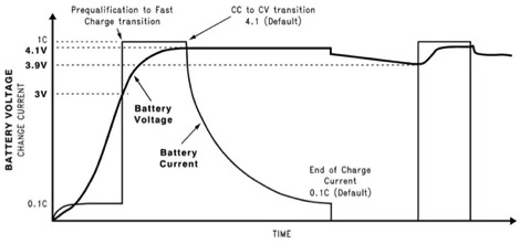

Figure 1: Constant Current/Constant Voltage Charging Profile
On the plot, there are values displayed as 0.1C and 1C; they represent a percentage of the battery’s C rating. A battery’s C rating refers to its capacity, and is the maximum safe amount of current that can be continuously supplied to or drawn from a battery. For example, if a battery has a 10Ah capacity, then a 1C rating is equivalent to safely charging the battery with 10A for one hour. Charging a 10Ah battery at 1C or 10A will fully charge it within one hour if the battery was initially at 0% SOC. A 0.1C rating is equivalent to safely charging the 10Ah battery with 1A for ten hours. In this CC/CV charging profile above, a battery is initially charged with 0.1C rated current until about 10% SOC because high currents at 0% SOC can cause overheating. The current is then increased to its 1C rating after a small period of time, and held at that constant current. During this constant current phase, the battery’s voltage rises to its maximum voltage. When the battery’s maximum voltage is reached, the charger applies a constant voltage, allowing the charging current to slowly decrease until the battery is full.
A CCCV charger is efficient and safe because it charges a battery at a constant maximum current for most of the battery’s capacity, preventing its maximum current from being exceeded. If a constant voltage source charges an empty battery at 0% SOC, the initial charging current can be greater than the maximum charging current. The output current of a constant voltage source is not regulated, making the source potentially dangerous for initial battery charging. In addition, if a battery is charged from 0% SOC to 100% SOC by just a constant voltage source, it will most likely take much longer to charge the battery to its full capacity. As a constant voltage source charges a battery, the battery’s voltage increases to the voltage source’s voltage and the charging current naturally decreases immediately. CCCV chargers, on the other hand, will provide a constant current to a battery. CCCV charging is also safe because it prevents overcharging when the charger converts from a constant current source to a constant voltage source. This prevents the voltage of a battery from increasing beyond the battery’s maximum voltage and allows the battery to continue drawing charge. To output a constant current, the charger must be regulated with feedback.
2.1.1 Implementation
To implement a CCCV charger, I ordered two constant current drivers from ICstation that were supposed to execute CCCV charging for battery charging applications. They both were supposed to draw power from a power supply as an input and supply power with a set voltage and current to a battery pack. These drivers can be seen below.

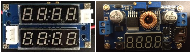
Figure 2: ICStation Current Drivers – CCCV Charger Application
The charger in the left image did not output as expected originally so I will focus on the charger in the right image. Below is a simple tutorial for the charger in the right image.
Ratings
-
Input Voltage: 5-36 VDC
-
Output Voltage: 1.25-32 VDC
-
Output Current Range: 0-5 A
-
Output Power: 75W
Display
-
Digital Clock and buttons on the bottom of the board
-
Potentiometers for Voltage and Current Control on top of the board
-
Input screw terminals on the left side of the board
-
Output screw terminals on the right side of the board
Instructions for the Operation of CCCV Charger
-
Plug in power to the input terminals IN+ and IN- ( confirm sufficient voltage and current)
-
Turn the left potentiometer to set the maximum voltage of the charger’s output
-
Turn the potentiometer screw clockwise to increase value and counterclockwise to decrease value
-
-
Short the output terminals
-
Turn the right potentiometer to set the maximum current limit
-
Turn the potentiometer screw clockwise to increase value and counterclockwise to decrease value
-
-
Left button displays input voltage
-
Right button displays output voltage, current, and power through multiple presses
-
Remove the short between the output terminals
-
The charger is ready to begin charging; simply connect OUT+ to the positive terminal of the battery pack and OUT- to the negative terminal of the battery pack
Theoretically, the charger was supposed to first output a constant current, equivalent to the set current limit, and then output a constant voltage, equivalent to the set maximum voltage. This charger would therefore execute CCCV charging.
2.1.2 Experimentation and Results
Before implementing a CCCV charger, it should be noted that I initially used a constant voltage source to charge a battery pack, containing five LiFePO4 cells in series. These cells were monitored by the battery management system (BMS) Orion BMS to prevent overcharging. As expected, the charging current was initially high, but rapidly decreased to a low current as the battery pack’s voltage increased. When testing the CCCV charger, I initially used an 18V, 0.5A rated power supply to provide the input power to the charger. This means that the maximum output voltage of the charger was 18V. The battery pack’s maximum voltage was roughly 18.5V to 19V, but I attempted to charge the pack to 18V due to the power supply’s limitation. However, I did not obtain the desired CCCV charging profile when I first tested the charger. The power supply prevented the charger from outputting constant current. I obtained a new laptop charger power supply with an adjustable voltage rating from 15v to 24V and a power rating of 70W.
I set the output voltage of the power supply to 19.5V, which means the CCCV charger’s input was 19.5V, allowing it to output 19V. The positive terminal OUT+ of the charger was connected to the positive terminal of the battery pack with a diode in series with it to prevent reverse current flow. The negative terminal OUT- of the charger was connected to the negative terminal of the battery pack. When I began charging the battery pack with the CCCV charger, the charger was able to output a constant current of approximately 0.5A for most of the battery pack’s state of charge. However, the charger did not completely finish charging the battery pack because the Orion BMS switched off the charging path when a cell’s voltage reached the maximum cell voltage of 3.8V. The CCCV charger was not provided enough time to allow the current to drop to 0A. This can be seen below in the following two plots. In the second plot, the current is a negative value because the current is flowing into the battery pack rather than out of the battery pack. The current also shows a value between 0.4A and 0.5A; however, the current is actually a constant 0.5A, but the Orion BMS is limited by low precision current measurements.
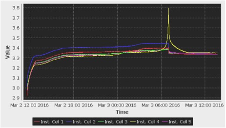

Figure 3: Cell Voltages vs Time During CCCV Charging – 3.8Vmax Achieved
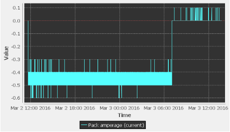

Figure 4: Pack Current vs Time During CCCV Charging – 0.5A Constant Current
2.2 Battery Characterization – Internal Resistance Tests
2.2.1 Implementation
I characterized the LiFePO4 cells during my project in Fall 2015 so I will not show their voltage profiles here. However, I never performed internal resistance tests in Fall 2015 so I decided to test for the internal resistance of the LiFePO4 battery pack. Internal resistance is important to monitor because the capacity of a battery decreases as its internal resistance increases. It is crucial to know how much the battery’s internal resistance limits the capacity. Unfortunately, batteries’ internal resistances naturally increase as they age, reducing their shelf life. Also, a battery with a high internal resistance typically cannot supply high currents, limiting its applications.
To calculate the internal resistance of the five cell, LiFePO4 battery pack, I needed a few measurements: the open-circuit voltage (OCV) of the pack, the voltage of the pack under load, and the current flowing through the load during discharge. The internal resistance of the battery pack is equal to the difference between the pack’s OCV and pack’s voltage under load, divided by the current flowing through the load. The figure below illustrates the process of obtaining the measurements for the internal resistance. The battery in the left circuit is equivalent to the ideal voltage source in series with the internal resistance Rin in the right circuit. When the battery is not connected to a load, such as in the left circuit, its voltage Vb is equal to the open-circuit voltage Voc. When a load is connected to the battery, such as in the right circuit, there is a voltage drop internally due to the internal resistance. As a result, the battery voltage Vb = Voc – I * Rin. Using this equation, you can calculate the internal resistance.

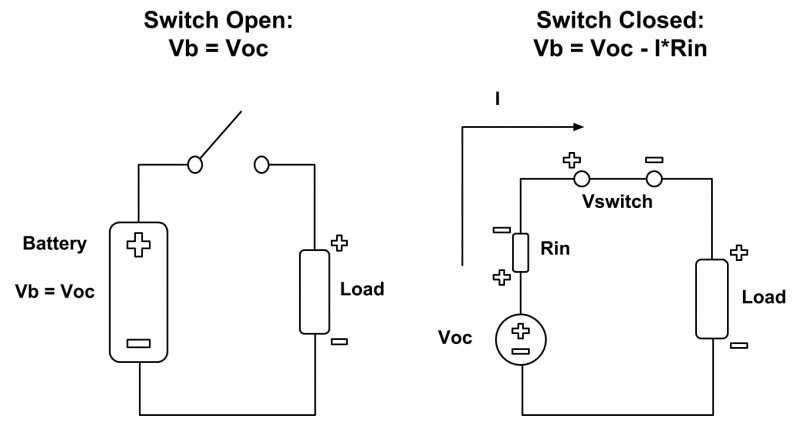 Figure 5: Equivalent Battery Configuration for Internal Resistance Tests
It should be noted that I included a voltage drop across the switch in the right circuit because my circuit in practice had some losses due to a SPST switch. The voltage across the load was not equal to the voltage across the battery pack.
2.2.2 Experimentation and Results
I calculated the current flowing through the load using Ohm’s law V = IR, such that R was the resistance of the load and V was the voltage across the load. I measured the resistance of the load as 15.2 ohms. I then performed several discharging pulses every few minutes and measured the open-circuit pack voltage, pack voltage under load, and voltage across the load. Below is an example of the discharge pulses.

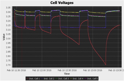
Figure 6: Cell Voltages vs Time During Discharge Pulses
Below are two tables of measurements that I took for these types of discharge pulse tests.

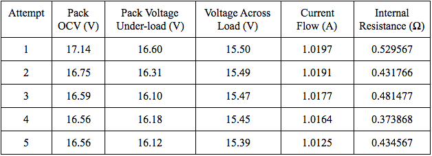

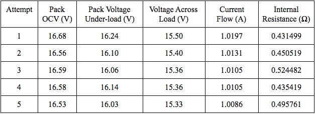
There are a few factors that may be responsible for the inaccurate results. One major factor is the rate at which I recorded the values. I did not record values at periodic intervals, nor did I allow the battery pack to discharge for the same amount of time more than once. To check my calculations for internal resistance, I should also perform tests of equal periods of time. Another major factor is that I did not allow the battery pack to relax for long enough periods to return to its true open-circuit voltage after discharging. Lithium ion batteries usually need an hour or more, depending on the current draw, for their voltages to return to their true open-circuit voltages. To analyze this phenomenon, I switched off the LiFePO4 pack’s discharge path multiple times and recorded the pack’s OCV every minute for thirty minutes. Below is a plot of the results of one test.
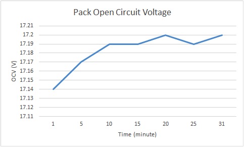

Figure 7: LiFePO4 Battery Pack’s Open Circuit Voltage vs Time
The battery pack’s open-circuit voltage increased slowly over 30 minutes, and could possibly have kept increasing. This change in OCV should be taken into account in the future for internal resistance tests. In addition, the results were limited by the precision of the multimeter that I used to measure the voltages. The multimeter only displayed up to the hundredths place; a multimeter with higher precision would obviously show more accurate measurements.
2.3 Customized Cycler
2.3.1 Implementation
Before discussing the implementation, it should be noted that I implemented a customized cycler for a single cell rather than for a battery pack because it was simpler to first focus on a single cell application. The cycler should be able to function as a battery pack cyler by adjusting a few parameters. To implement a customized cycler, I used four main components: a BeagleBone Black, a CCCV charger, a resistive load, and a relay module board. A sketch of the circuit can be seen below.
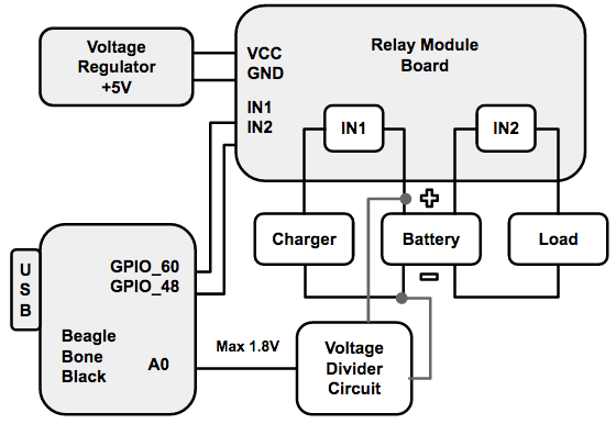

Figure 8: Schematic of Battery Cycler
The BeagleBone Black is a development platform and single-board computer. It executed a cycling algorithm and controlled the cycling process. The CCCV charger and resistive load performed the actual cycling. The relay module board was controlled by the BeagleBone Black, and was responsible for automatically switching the charging and discharging paths. The relay module board was powered with 5V. I used two relays on the module board, one for the charging path and the other for the discharging path. Each relay has three terminals: COM, NC, and NO. NC stands for normally connected, COM stands for common, and NO stands for normally open. As one could imagine, COM and NC are normally connected when the relay is not energized, but when the relay is activated, COM toggles and connects to NO. To use these relays for the charging or discharging paths, you simply have to connect the positive terminal of a cell to COM on both relays, connect the positive terminals of the charger or load to NO on their separate relays, and connect all of their negative terminals together. When the relays are energized, COM and NO connect, allowing for the cell to either charge or discharge. It should be noted that both relays should not be activated at the same time.
The relay module board has two active-low inputs, In1 and In2, corresponding to the two relays IN1 and IN2. When an input is set low to 0V or GND, the corresponding relay is activated, connecting the COM to NO on that relay. The BeagleBone Black has digital outputs, labeled as GPIO pins in the diagram, which are high by default, but can be set low with a command. By programming the BeagleBone Black, I was able to output low values to the In1 and In2 inputs on the relay board, activating the corresponding relays. The BeagleBone Black also has an analog input, labeled as A0, that can measure the voltage of the battery. However, the maximum voltage of the input into A0 is 1.8V. Therefore, I used a voltage divider to shift the voltage of the battery into a smaller range between 0 and 1.8V. The two resistors were: R1 = 98.9 kOhm and R2 = 56.55 kOhm. The resistors must have large resistances, such that they draw negligible current from the cell. In the Experimentation section below, I will discuss the cycling algorithm that ties all of the functionality together.
2.3.2 Experimentation and Results
Before testing the cycler with the single cell, I performed various experiments to confirm that it worked properly. I proved that I could control two relays on the module board and measure a voltage with the analog input pin separately with the BeagleBone Black. I then performed both functions and executed a cycling algorithm without the battery. The BeagleBone Black controlled the relays, switching them on and off based on the output voltage of a voltage regulator. I manually increased and decreased the regulator’s output voltage, such that it would simulate a battery being charged and discharged. After showing that the functionality worked together, I connected the charging and discharging circuits to the appropriate relays and tested the complete cycler with a single LiFePO4 cell. Below is a flowchart of the cycling algorithm for a single cell.
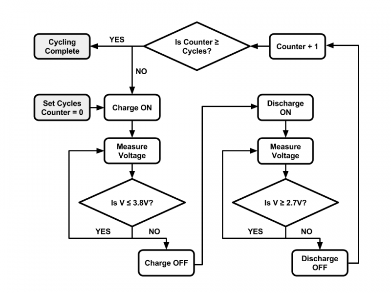
 Figure 9: Flowchart of Cycling Algorithm for Single LiFePO4 Cell
The maximum and minimum voltages are set in the code, prior to cycling. In this algorithm, I used the parameters of a LiFePO4 single cell. A user sets the number of times that the battery should cycle. The algorithm keeps track of the number of cycles completed using a counter. The cycler turns on the charging path using a relay and charges the battery continuously until the maximum voltage is reached. The cycler then turns off the charging path, turns on the discharging path using another relay, and discharges the battery continuously until the minimum voltage is reached. The cycler increments the counter and compares it the number of cycles requested to see if it should repeat the process or stop cycling. Below is the code that implements the algorithm. It is written with Python 2.7.1 in the linux terminal on the BeagleBone Black.

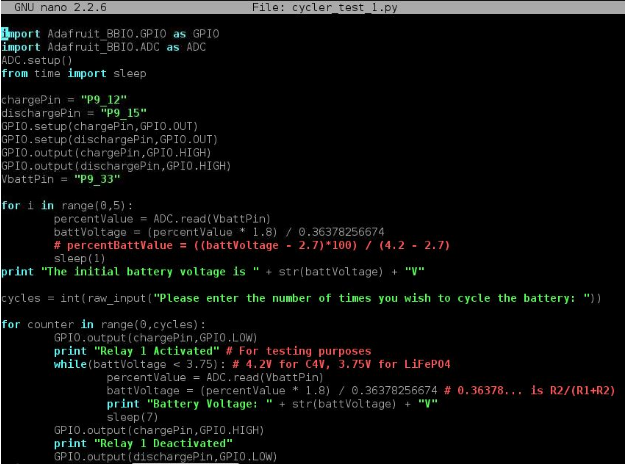


Figure 10: Cycling Program for Battery Cycler
The constant 0.36378256674 used in the code above is actually the ratio R2/ (R1 + R2) of the voltage divider. As stated above, I used two resistors in the voltage divider: R1 = 98.9 kOhm and R2 = 56.55 kOhm. To demonstrate a short test of the cycler’s performance, I charged a single LiFePO4 cell to 3.7V separately and tested it with the cycler afterwards. I set the maximum voltage to 3.75V because I didn’t want the cell’s voltage to actually reach beyond its true maximum voltage 3.8V. In the terminal, you can see that I set the cycler to cycle two times. Relay 1 was energized, allowing the battery to charge. When the voltage reached beyond 3.75V, relay 1 was deenergized and relay 2 was energized, allowing the battery to discharge. I interrupted the program to end it because I did not want to fully cycle the battery.

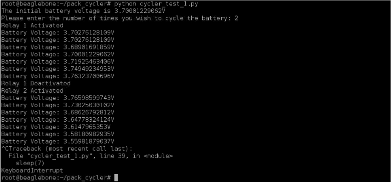 Figure 11: Results from Quick Cycler Test
III. Conclusion
3.1 Results
In conclusion, I completed three main tasks during this independent study. I obtained and tested a CCCV charger, performed several tests for the internal resistance of a LiFePO4 battery pack, and developed a single cell cycler. The CCCV charger was able to perform constant current charging and constant voltage charging on the LiFePO4 battery pack. However, the CCCV charger was not provided enough time to show the constant voltage phase of CCCV charging immediately after the constant current phase because the Orion BMS turned off the charging path. The CCCV charger initially output a constant voltage across the LiFePO4 battery pack though when its power was limited by the power supply. To show both phases of CCCV charging, you must use a balanced battery pack, such that the Orion BMS won’t turn off the charging path when a maximum cell voltage is reached. I completed several tests for the internal resistance of the battery pack, but the results were inconclusive. The tests were limited by the precision of the multimeter and the relaxation time of the battery pack after discharge. I also developed a single cell cycler using a BeagleBone Black, charging and discharging circuit, and relay module board. I successfully charged and discharged a LiFePO4 cell for a short period of time with the cycler. However, the cycler did not perform CCCV charging because it needs a current sensor to implement this functionality. In the next steps section, I discuss ways to improve the cycler and scale it for a battery pack application.
3.2 Next Steps
There are a few steps that can be taken to improve the battery cycler. One step is to scale the cycler’s use for a battery pack rather than a single cell. This can be completed by making a few modifications to the current setup. The charger can be set to a higher charging voltage (19V) and the load can be configured as a 15 ohm load. New resistors can be selected for the voltage divider to shift the battery pack’s voltage range from a higher voltage to a 0 – 1.8V range. The maximum and minimum voltage parameters can be changed in the cycling program. In addition, the BeagleBone Black offers several analog inputs, which could potentially measure the individual cell voltages. This is very important because you want to make sure the cell voltages do not exceed the maximum cell voltage. Another step is to purchase a current sensor and integrate it into the cycler. By measuring the current into the battery pack during the constant voltage period of charging, the cycler can turn the charging path off when the current drops to a minimum value. To perform this functionality, you would have to adjust the cycling algorithm such that the charging cycle turns off after the output current reaches a certain minimum value rather than the battery voltage reaches the maximum voltage. Also, a SOC algorithm could be introduced into the cycler, such that it integrates the current over time and keeps track of the battery pack’s state of charge.
IV. References
[1] “Battery and Energy Technologies.” Lithium Battery Failures. Electropaedia, 2005. Web. <http://www.mpoweruk.com/lithium_failures.htm>.
[2] “A Designer’s Guide to Lithium Battery Charging.” Digi-Key Electronics. Steven Keeping, 25 Sept. 2012. Web. <http://www.digikey.com/en/articles/techzone/2012/sep/a-designers-guide-to-lithium-battery-charging>