Solar cell shading and the use of bypass Diode to resolve the shading
Spring 2016
Winfred Asante
Table of Contents
A. Introduction
II. Motivation
III. Problem Statement
V. How to mitigate solar shading
B. Research
VI. Bypass Diode
VII. Implementation and Results
C. VII. Conclusion
IX. Limitations
X. Future works
D.XI. References
I. Introduction
The following independent study will focus solar cell shading and how to mitigate it in order to improve the overall power output using Matlab-Simulink simulation environment
II. Motivation
The growing desire for energy sources and environmental concerns about fossil fuels has lead exponential growth in the demand for clean renewable energy resources. Solar (photovoltaic, PV) energy has received notable research, investment. Since, solar energy is abundant, and can be easily scaled up.
In the first half of 2015, the solar industry has supplied 40% of all new 2015 electric generating capacity – more than any other energy technology. With more than 5,000 MW of installed solar capacity projected over the second half of 2015, the U.S. solar industry is expected to reach nearly 8,000 MW for the year, and 28,000 MW in total.
The use of photovoltaic solar cells is emerging as one of the fastest growing green energy technologies. Several mega-watt solar farms are being continuously deployed all over the world. In such large farms, shading plays a critical role. Shading is mainly caused due to dust settlement in panels, passing cloud and shadows of neighboring mounting structures. Due to shading, the real power generated from a solar PV array may fall far below the designed level, which at times may lead to a complete “loss of load” it can also result in failure of commonly used MPPT controllers.
This project would cover the use of bypass diode in resolving solar shading to improve IV output of solar cells. The design and implementation would be done in simulink Matlab platform.
III. Problem Statement
IV. Effects of shading
Partial shading can cause solar cells to operate with negative bias voltages ranging from -4V to -25V compared to the more typical operating (forward bias) voltage of approximately +0.6V for individual cells when modules are uniformly illuminated. The reverse operation of the solar cell or module due to shading can lead to permanent damage to PV module and lower power output.
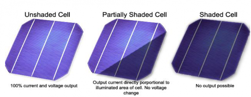
Figure 1: a). no shading b).partial shading c) total shading
The output of a PV module can be reduced dramatically when even when a small portion of it is shaded. For example, when one solar cell is shaded while the remainder in the module are not, some of the power being generated by the “sunny” solar cells can be dissipated by the “shaded” cell rather than powering the load. – This in turn can lead to highly localized power dissipation and the resultant local heat may cause irreversible damage to the module
A reverse voltage (applied by other cells) will cause the cell to consume power. A significant reverse voltage will result in irreparable damage.
• If forward voltage that is greater than the cell open-circuit voltage is applied (by an external source), current starts to flow into the cell. The cell begins to consume power.
· Now let consider when the cell is fully shaded
· Since the current I generated by the non-shaded cell travels through the shaded cell becomes reverse biased, i.e., negative voltage equal to
Appears across its terminals.
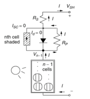
Figure 2a: top shaded cell
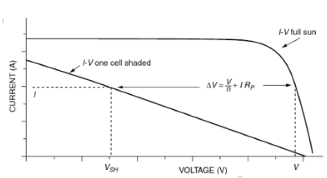
Figure 2b: shows a current voltage plot
V. How to Mitigate Shading
To achieve high reliability and performance, especially in shaded environments, a bypass diode is connected parallel with the solar cell or module. It must be noted that solar cells with large VBR are susceptible to permanent damage and high power losses hence the need for bypass diodes with higher ratings. On other hand cells with low VBR are at less risk for damage.
Main parameters of solar cells Short circuit current (Isc) and open circuit voltage (Voc)
The solar cells or panel are usually characterized by their short circuit current (Isc) and their open circuit voltage (Voc).
The short circuit current (Isc) is the current generated by the solar cell or panel when output voltage of the cell or panel is set to 0 V.
RS/RP and RS being negligible, the short circuit current is close to the photocurrent IL generated by the cell and is the maximum possible current generated by the cell for a fixed illumination.
VI. Bypass diode
The bypass diode principle is to use a diode in reverse paralleling with several solar cells. The bypass diode is blocked when all cells are illuminated, and conducts when one or several cells are shadowed.
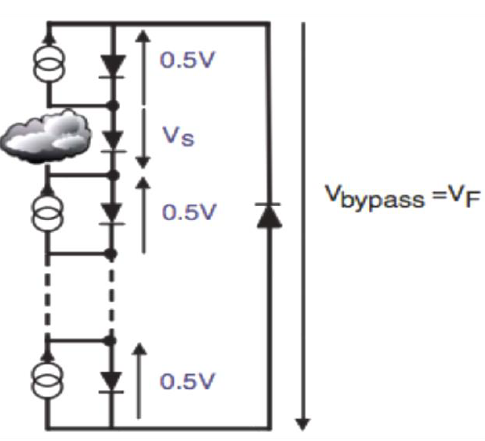
Figure 3: bypass diode principle
VRRM of bypass diode
Knowing the number of bypass diodes nd and the Voc of the panel, the maximum repetitive reverse voltage (VRRM) of the bypass diode can be calculated. In the worst case, the bypass diode reverse voltage is equal to the open circuit voltage (Voc_max) of the solar panel divided by the number of bypass diodes nd. Voc_max is the open circuit voltage at the minimum ambient temperature with the maximum irradiance.
VII. Implementation and results
Design for One Shaded cell with for IV curves Diode
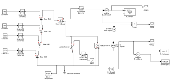
The implementation was design using Matlab and simulink
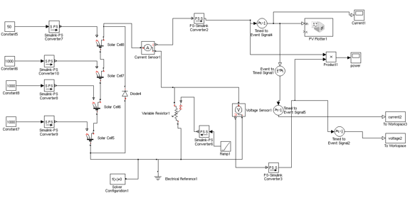
Figure 4: matlab-simulink design for One Diode per four cells
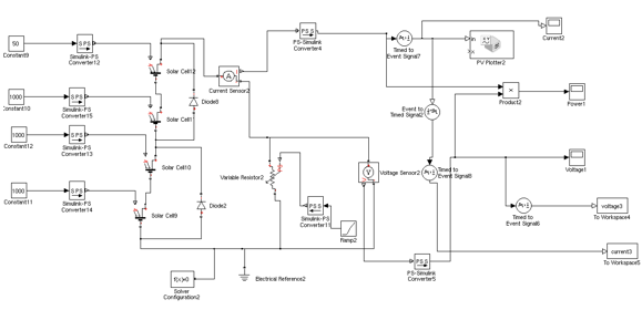
Figure 5: matlab-simulink design for One Diode per Two cells
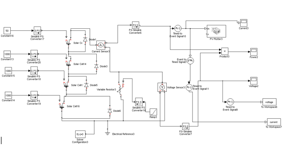
Figure 6: matlab-simulink design for One Diode per cell
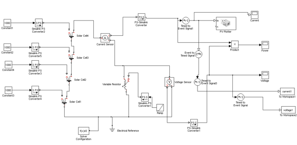
Figure 7: matlab-simiulink desgn for no Diode
Results
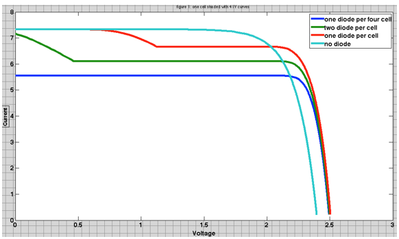
Figure 8: matlab plots of IV curves for all the four designs above
Design for Two Shaded cells with Four IV curves
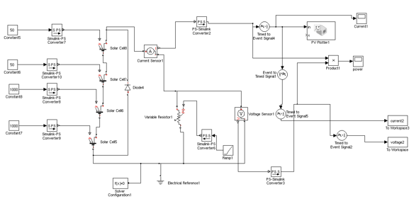
Figure 9: matlab-simulink design for Two shaded cell with one diode
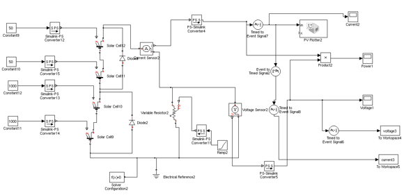
Figure 10: matlab-simulink design for Two shaded cells with Two diodes
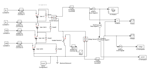
Figure 11: matlab-simulink design for Two shaded cells with Four diodes
Fiure 12: matlab-simulink design for no shaded cell
Results
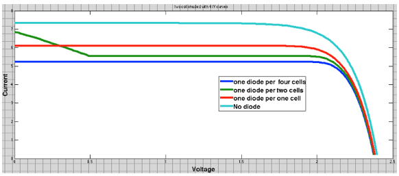
Figure 13: matlab plots of IV curves for all four designs above
VIII. Conclusions
The power output of shaded solar cell can be improved by the connecting a bypass diode parallel to the shaded cell. From the plots above, the IV curve can be improved by connecting a bypass diode across each solar cell as shown in figure 11.
IX. Limitations
Difficulties in choice of diode ratings
Difficulties in using XY- scope of Simulink for multiple plots
X. Future work
Implementation in a PV module environment
Testing with actual solar cells and module
XI. References
Singh, A. K., & Tripathi, R. K. (2012, March). MPPT scheme for small/large time partially shaded condition of a PV cell, array. In Engineering and Systems (SCES), 2012 Students Conference on (pp. 1-4). IEEE.
Sera, Dezso, and Yahia Baghzouz. “On the impact of partial shading on PV output power.” WSEAS/IASME International Conference on Renewable Energy Sources (RES’08). 2008.
http://www.egr.unlv.edu/~eebag/Photovoltaic%20Devices%20III.pdf